8. Hybrid Multi-Cloud: Data Centre to Edge 
Table of Contents 
8.1 Introduction 
The Reference Model Chapter 3 focuses on cloud infrastructure abstractions. While these are generic abstractions they and the associated capabilities of the cloud infrastructure are specified for data centres, central office and colocation centres. The environmental conditions, facility and other constraints, and the variability of deployments on the edge are significantly different and, thus, require separate consideration.
It is unrealistic to expect that a private cloud can cost effectively meet the need of all loads, including peak loads and disaster recovery. It is for that reason that enterprises will implement a hybrid cloud. In a hybrid cloud deployment, at least two or more distinct cloud infrastructures are inter-connected together. In a multi-cloud the distinct cloud infrastructures of the hybrid cloud may be implemented using one or more technologies. The hybrid multi-cloud infrastructure has differences requiring different abstractions. These hybrid multi-clouds can be considered to be federated.
In the Reference Model Chapter 3 , the cloud infrastructure is defined. The tenants are required to provide certain needed services (such as Load Balancer (LB), messaging). Thus, the VNF/CNFs incorporate different versions of the same services with the resultant issues related to an explosion of services, their integration and management complexities. To mitigate these issues, the Reference Model must specify the common services that every Telco cloud must support and thereby require workload developers to utilise these pre-specified services.
A generic Telco cloud is a hybrid multi-cloud or a Federated cloud that has deployments in large data centres, central offices or colocation facilities, and the edge. This chapter discusses the characteristics of Telco Edge and hybrid multi-cloud.
8.2 Hybrid Multi-Cloud Architecture 
The GSMA whitepaper on “Operator Platform Concept Phase 1: Edge Cloud Computing” (January 2020) states, “Given the wide diversity of use cases that the operators will tasked to address, from healthcare to industrial IoT, it seems logical for operators to create a generic platform that can package the existing assets and capabilities (e.g., voice messaging, IP data services, billing, security, identity management, etc. …) as well as the new ones that 5G makes available (e.g., Edge cloud, network slicing, etc.) in such a way as to create the necessary flexibility required by this new breed of enterprise customers.”
Cloud computing has evolved and matured since 2010 when NIST published its definition of cloud computing, with its 5 essential characteristics, 3 service models and 4 deployment models.
The generic model for an enterprise cloud has to be “hybrid” with the special cases of purely private or public clouds as subsets of the generic hybrid cloud deployment model. In a hybrid cloud deployment, at least two or more distinct cloud infrastructures are inter-connected together.
Cloud deployments can be created using a variety of technologies (e.g., OpenStack, Kubernetes) and commercial technologies (e.g., VMware, AWS, Azure, etc.). A multi-cloud deployment can consist of the use of more than one technology.
A generic Telco cloud is a hybrid multi-cloud. A better designation would be a federation of clouds - a federated cloud:
-
a collection of cooperating, interoperable autonomous component clouds
-
the component clouds perform their local operations (internal requests) while also participating in the federation and responding to other component clouds (external requests)
-
the component clouds are autonomous in terms of, for example, execution autonomy; please note that in a centralised control plane scenario (please see the section “Centralised Control Plane” in the “ Edge Computing: Next Steps in Architecture, Design and Testing ” whitepaper [26]) the edge clouds do not have total autonomy and are subject to constraints (e.g., workload LCM)
-
execution autonomy is the ability of a component cloud to decide the order in which internal and external requests are performed
-
-
the component clouds are loosely coupled where no changes are required to participate in a federation
-
also, a federation controller does not impose changes to the component cloud except for running some central component(s) of the federated system (for example, a broker agent – executes as a workload)
-
-
the component clouds are likely to differ in, for example, infrastructure resources and their cloud platform software
-
workloads may be distributed on single or multiple clouds, where the clouds may be collocated or geographically distributed
-
component clouds only surface NBIs (Please note that VMware deployed in a private and a public cloud can be treated as a single cloud instance)
8.2.1 Characteristics of a Federated Cloud 
In this section we will further explore the characteristics of the federated cloud architecture, and architecture building blocks that constitute the federated cloud. For example, Figure 8-1 shows a Telco Cloud that consists of 4 sub-clouds: Private on premise, Cloud Vendor provided on premise, Private outsourced (Commercial Cloud Provider such as a Hyperscaler Cloud Provider (HCP), and Public outsourced (see diagram below). Such an implementation of a Telco Cloud allows for mix’n’match of price points, flexibility in market positioning and time to market, capacity with the objective of attaining near “unlimited” capacity, scaling within a sub-cloud or through bursting across sub-clouds, access to “local” capacity near user base, and access to specialised services.

Figure 8-1: Example Hybrid Multi-Cloud Component Cloud
8.2.2 Telco Cloud 
The Figure 8-2 presents a visualisation of a Telco operator cloud (or simply, Telco cloud) with clouds and cloud components distributed across Regional Data Centres, Metro locations (such as Central Office or a Colocation site) and at the Edge, that are interconnected using a partial mesh network. Please note that at the Regional centre level the interconnections are likely to be a “fuller” mesh while being a sparser mesh at the Edges.
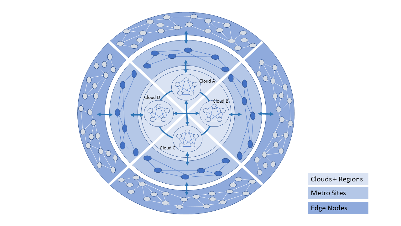
Figure 8-2: Telco Cloud: Data Centre to Edge
The Telco Operator may own and/or have partnerships and network connections to utilize multiple Clouds for network services, IT workloads, and external subscribers. The types of the component clouds include:
-
On Premise Private
-
Open source; Operator or Vendor deployed and managed | OpenStack or Kubernetes based
-
Vendor developed; Operator or Vendor deployed and managed | Examples: Azure on Prem, VMware, Packet, Nokia, Ericsson, etc.
-
-
On Premise Public: Commercial Cloud service hosted at Operator location but for both Operator and Public use | Example: AWS Wavelength
-
Outsourced Private: hosting outsourced; hosting can be at a Commercial Cloud Service | Examples: Equinix, AWS, etc.
-
(Outsourced) Public: Commercial Cloud Service | Examples: AWS, Azure, VMware, etc.
-
Multiple different Clouds can be co-located in the same physical location and may share some of the physical infrastructure (for example, racks)
In general, a Telco Cloud consists of multiple interconnected very large data centres that serve trans-continental areas (Regions). A Telco Cloud Region may connect to multiple regions of another Telco Cloud via large capacity networks. A Telco Cloud also consists of interconnected local/metro sites (multiple possible scenarios). A local site cloud may connect to multiple Regions within that Telco Cloud or another Telco Cloud. A Telco Cloud also consists of a large number of interconnected edge nodes where these edge nodes maybe impermanent. A Telco Cloud’s Edge node may connect to multiple local sites within that Telco Cloud or another Telco Cloud; an Edge node may rarely connect to a Telco Cloud Region.
Table 8-1 captures the essential information about the types of deployments, and responsible parties for cloud artefacts.
|
Type |
System D eveloper |
System Mai ntenance |
System Operated & Managed by |
Location where Deployed |
Primary Resource Con sumption Models |
|---|---|---|---|---|---|
|
Private ( Internal Users) |
Open Source |
Sel f/Vendor |
Sel f/Vendor |
On Premise |
R eserved, D edicated |
|
Private |
Vendor | HCP |
Sel f/Vendor |
Sel f/Vendor |
On Premise |
R eserved, D edicated |
|
Public |
Vendor | HCP |
Sel f/Vendor |
Sel f/Vendor |
On Premise |
R eserved, On Demand |
|
Private |
HCP |
Vendor |
Vendor |
Vendor L ocations |
R eserved, D edicated |
|
Public (All Users) |
HCP |
Vendor |
Vendor |
Vendor L ocations |
On Demand, Reserved |
Table 8-1. Cloud Types and the Parties Responsible for Artefacts
8.2.3 Telco Operator Platform Conceptual Architecture 
Figure 8-3 shows a conceptual Telco Operator Platform Architecture. The Cloud Infrastructure Resources Layer exposes virtualised (including containerised) resources on the physical infrastructure resources and also consists of various virtualisation and management software (see details later in this chapter). The Cloud Platform Components Layer makes available both elementary and composite objects for use by application and service developers, and for use by Services during runtime. The Cloud Services Layer exposes the Services and Applications that are available to the Users; some of the Services and Applications may be sourced from or execute on other cloud platforms. Please note that while the architecture is shown as a set of layers, this is not an isolation mechanism and, thus, for example, Users may access the Cloud Infrastructure Resources directly without interacting with a Broker.
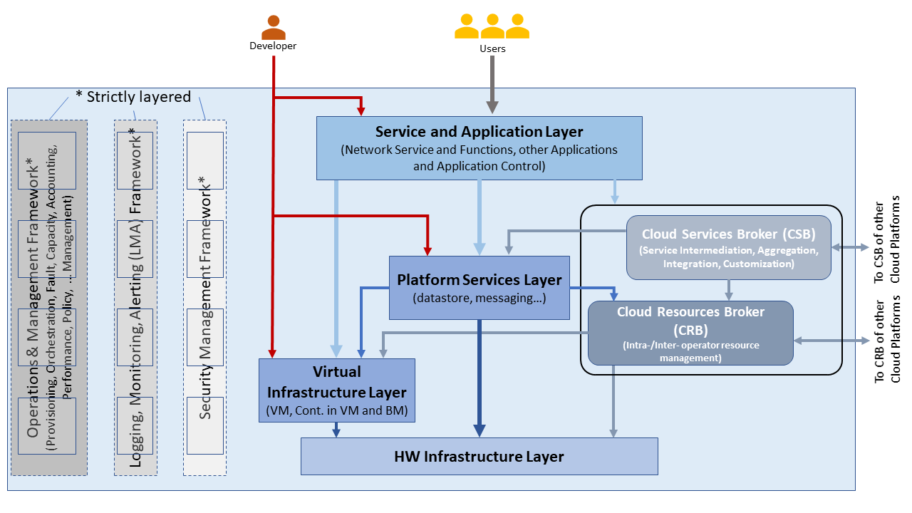
Figure 8-3: Conceptual Architecture of a Telco Operator Platform
The Cloud Services and the Cloud Resources Brokers provide value-added services in addition to the fundamental capabilities like service and resource discovery. These Brokers are critical for a multi-cloud environment to function and utilise cloud specific plugins to perform the necessary activities. These Brokers can, for example, provision and manage environments with resources and services for Machine Learning (ML) services, Augmented/Virtual Reality, or specific industries.
8.2.4 Multi-Cloud Interactions Model 
8.2.5 Aspects of Multi-Cloud Security 
Cloud infrastructures, emerging as a key element in the telco operator ecosystem, are part of the attack surface landscape. This is particularly worrying with the 5G rollout becoming a critical business necessity. It is important to be vigilant of Cloud-focused threats and associated adversarial behaviours, methods, tools, and strategies that cyber threat actors use.
In the multi-cloud ecosystem comprised of different security postures and policies, network domains, products, and business partnerships, the responsibility for managing these different cloud environments necessary to support 5G use cases falls to different enterprises, creating new levels of complexities and a new range of security risks. In such an environment, there are additional security principles to be considered. These principles, see Table 8-1a below, are drawn from the collaboration with the GSMA Fraud and Security Group (FASG).
|
Multi-cloud Security Principle |
Description |
|---|---|
|
Policy synchronization |
Consistency in applying the right security policies across environments, services, interfaces, and configured resources |
|
Visibility |
A common data model approach to share events and behaviours across all the key compute, storage, network, and applications resources, environments, virtualised platforms, containers and interfaces |
|
Monitoring |
Centralisation, correlation, and visualisation of security information across the different cloud environments to provide an end-to-end view and enable timely response to attacks |
|
Automation |
Automation of critical activities including cloud security posture management, continuous security assessments, compliance monitoring, detection of misconfigurations and identification and remediation of risks |
|
Access Management |
Wide range of users including administrators, testers, DevOps, and developers and customers should be organised into security groups with privileges appropriate to different resources and environments |
|
Security Operations Model |
Augmentation of security services provided by cloud service providers with the vetted third-party and/or open-source tools and services, all incorporated into the established overall security operations model |
Table 8-1a. Multi-Cloud Principles
For telco operators to run their network functions in a multi-cloud environment, and specifically, in public clouds, the industry will need a set of new standards and new security tools to manage and regulate the interactions between multi-cloud participating parties. To give an example of a step in this direction, refer to the ETSI specification TS 103 457 “Interface to offload sensitive functions to a trusted domain”, which provides extra security requirements for public clouds so as to enable telco operators the option of running network functions in public clouds.
There is also another security aspect to consider, which is related to the autonomous nature of the participants in the multi-cloud. We can prescribe certain things and if not satisfied treat that party as “untrusted”. This problem has been addressed to some extent in TS 103 457. This standard introduces a concept of an LTD (Less Trusted Domain) and an MTD (More Trusted Domain) and specifies the TCDI (Trusted Cross-Domain Interface) to standardise secure interactions between them. The standard defined the following elementary functions of TCDI: Connection and session management Data and value management Transferring cryptography functionality:
-
Entropy request
-
Encryption keys request
-
Trusted timestamping
-
Secure archive
-
Secure storage
-
Search capabilities
As described in Sec. 1 (Scope) of the TS 103 45 document, it specifies “… a high-level service-oriented interface, as an application layer with a set of mandatory functions, to access secured services provided by, and executed in a More Trusted Domain. The transport layer is out of scope and left to the architecture implementation”. The standard provides extra security features for sensitive functions down to individual Virtual Machines or Containers. As such, it is recommended that the relevant components of reference models, reference architecture, reference implementations and reference compliance take notice of this standard and ensure their compatibility, wherever possible.
8.3 Telco Edge Cloud 
This section presents the characteristics and capabilities of different Edge cloud deployment locations, infrastructure, footprint, etc. Please note that in the literature many terms are used and, thus, this section includes a table that tries to map these different terms.
8.3.1. Telco Edge Cloud: Deployment Environment Characteristics 
Telco Edge Cloud (TEC) deployment locations can be environmentally friendly such as indoors (offices, buildings, etc.) or environmentally challenged such as outdoors (near network radios, curb side, etc.) or environmentally harsh environments (factories, noise, chemical, heat and electromagnetic exposure, etc). Some of the more salient characteristics are captured in Table 8-2.
|
F acility Type |
Enviro nmental C haracte ristics |
Capab ilities |
P hysical S ecurity |
Impli cations |
Dep loyment Lo cations |
|
|---|---|---|---|---|---|---|
|
E nvironm entally f riendly |
I ndoors: typical com mercial or resi dential str uctures |
Protec tedSafe for common infrast ructure |
Easy access to con tinuous e lectric po werHigh /Medium ba ndwidth Fixed and/or w ireless network access |
Con trolled Access |
Commo ditised infrast ructure with no or minimal need for harden ing/rug gedisat ionOper ational b enefits for insta llation and main tenance |
Indoor venues: homes, shops, o ffices, sta tionary and secure cabin etsData c enters, central o ffices, co-l ocation faci lities, Vendor pr emises, C ustomer p remises |
|
E nvironm entally cha llenged |
O utdoors and/or exposed to e nvironm entally harsh con ditions |
maybe unpro tectedE xposure to a bnormal levels of noise, vib ration, heat, ch emical, e lectrom agnetic po llution |
May only have battery p owerLow /Medium ba ndwidth Fixed and/or mobile network access |
No or minimal access control |
Ex pensive rugge disatio nOperat ionally complex |
Example loc ations: curb side, near c ellular radios, |
Table 8-2. TEC Deployment Location Characteristics & Capabilities
8.3.2 Telco Edge Cloud: Infrastructure Characteristics 
Commodity hardware is only suited for environmentally friendly environments. Commodity hardware have standardised designs and form factors. Cloud deployments in data centres typically use such commodity hardware with standardised configurations resulting in operational benefits for procurement, installation and ongoing operations.
In addition to the type of infrastructure hosted in data centre clouds, facilities with smaller sized infrastructure deployments, such as central offices or co-location facilities, may also host non-standard hardware designs including specialised components. The introduction of specialised hardware and custom configurations increases the cloud operations and management complexity.
At the edge, the infrastructure may further include ruggedised hardware for harsh environments and hardware with different form factors.
8.3.3 Telco Edge Cloud: Infrastructure Profiles 
The Cloud Infrastructure Profiles section specifies two infrastructure profiles:
The Basic cloud infrastructure profile is intended for use by both IT and Network Function workloads that have low to medium network throughput requirements.
The High Performance cloud infrastructure profile is intended for use by applications that have high network throughput requirements (up to 50Gbps).
The High Performance profile can specify extensions for hardware offloading; please see Hardware Acceleration Abstraction . The Reference Model High Performance profile includes an initial set of High Performance profile extensions .
Based on the infrastructure deployed at the edge, Table 8-3 specifies the Infrastructure Profile features and requirements that would need to be relaxed.
Table 8-3. TEC Exceptions to Infrastructure Profile features and requirements
|
Re ference |
Feature |
Desc ription |
As Sp ecified in RM Chapter 05 |
Ex ception for Edge |
||
|---|---|---|---|---|---|---|
|
Basic Type |
High Perfor mance |
Basic Type |
High Perfor mance |
|||
|
inf ra.stg. cfg.003 |
Storage with repl ication |
N |
Y |
N |
O ptional |
|
|
inf ra.stg. cfg.004 |
Storage with enc ryption |
Y |
Y |
N |
O ptional |
|
|
infra. hw.cpu. cfg.001 |
Minimum Number of CPU sockets |
This det ermines the minimum number of CPU sockets within each host |
2 |
2 |
1 |
1 |
|
infra. hw.cpu. cfg.002 |
Minimum Number of cores per CPU |
This det ermines the number of cores needed per CPU. |
20 |
20 |
1 |
1 |
|
infra. hw.cpu. cfg.003 |
NUMA al ignment |
NUMA al ignment support and BIOS con figured to enable NUMA |
N |
Y |
N |
Y* |
* immaterial if the number of CPU sockets (infra.hw.cpu.cfg.001) is 1
Please note that none of the listed parameters form part of a typical OpenStack flavour except that the vCPU and memory requirements of a flavour cannot exceed the available hardware capacity.
8.3.4 Telco Edge Cloud: Platform Services Deployment 
This section characterises the hardware capabilities for different edge deployments and the Platform services that run on the infrastructure. Please note, that the Platform services are containerised to save resources, and benefit from intrinsic availability and auto-scaling capabilities.
Table 8-4. Characteristics of Infrastructure nodes
Depending on the facility capabilities, deployments at the edge may be similar to one of the following:
-
Small footprint edge device
-
Single server: deploy multiple (one or more) workloads
-
Single server: single Controller and multiple (one or more) workloads
-
HA at edge (at least 2 edge servers): Multiple Controller and multiple workloads
8.3.5 Comparison of Deployment Topologies and Edge terms 
Table 8-5. Comparison of Deployment Topologies
|
This Spe cific ation |
Co mpute |
St orage |
Netwo rking |
RTT |
Sec urity |
S calab ility |
Elast icity |
Resil iency |
Pref erred Wor kload Ar chite cture |
Upg rades |
Open Stack |
OPNFV Edge |
Edge Glo ssary |
GSMA |
|
|---|---|---|---|---|---|---|---|---|---|---|---|---|---|---|---|
|
Reg ional Data C entre (DC) Fixed |
1000’ sStan dardi sed>1 C PU>20 core s/CPU |
10’s EB Stand ardis edHDD and NVMe Perma nence |
>100 G bpsSt andar dised |
~100 ms |
H ighly S ecure |
Horiz ontal and unli mited sc aling |
Rapid spin up and down |
Infr astru cture a rchit ected for resil iency Redun dancy for FT and HA |
Mic roser vices based State lessH osted on Conta iners |
HW Ref resh: ? Firm ware: When r equir edPla tform SW: CD |
Ce ntral Data C entre |
||||
|
Metro Data Ce ntres Fixed |
10’s to 100’ sStan dardi sed>1 C PU>20 core s/CPU |
100’s PBS tanda rdise dNVMe on PCIe Perma nence |
> 100 G bpsSt andar dised |
~10 ms |
H ighly S ecure |
Horiz ontal but li mited sc aling |
Rapid spin up and down |
Infr astru cture a rchit ected for some level of resil iency Redun dancy for li mited FT and HA |
Mic roser vices based State lessH osted on Conta iners |
HW Ref resh: ? Firm ware: When r equir edPla tform SW: CD |
Edge Site |
Large Edge |
A ggreg ation Edge |
||
|
Edge Fixed / M obile |
10’ sSome Vari abili ty>=1 C PU>10 core s/CPU |
100 TBS tanda rdise dNVMe on PCIe Perma nence / Ephe meral |
50 G bpsSt andar dised |
~5 ms |
Low Level of Trust |
Horiz ontal but h ighly c onstr ained sca ling, if any |
Rapid spin up (when poss ible) and down |
Ap plica tions des igned for resil iency ag ainst infra failu resNo or h ighly li mited redun dancy |
Mic roser vices based State lessH osted on Conta iners |
HW Ref resh: ? Firm ware: When r equir edPla tform SW: CD |
Far Edge Site |
M edium Edge |
A ccess Edge / A ggreg ation Edge |
||
|
Mi ni-/M icro- EdgeM obile / Fixed |
1’ sHigh V ariab ility Harsh Env ironm ents1 CPU>2 core s/CPU |
10’s GB NVMeE pheme ralCa ching |
10 G bpsCo nnect ivity not Guara nteed |
<2 msLo cated in ne twork prox imity of EU D/IoT |
Untr usted |
Li mited Ver tical Sc aling (resi zing) |
C onstr ained |
Ap plica tions des igned for resil iency ag ainst infra failu resNo or h ighly li mited redun dancy |
Mic roser vices based or mono lithi cStat eless or Stat efulH osted on Conta iners or VMsSu bject to QoS, ada ptive to res ource ava ilabi lity, viz. r educe res ource c onsum ption as they sat urate |
HW Ref resh: ? Firm ware: ? Pla tform SW: ? |
Fog Comp uting (M ostly depre cated term inolo gy)Ex treme Ed geFar Edge |
Small Edge |
A ccess Edge |